OctalWheels for Manual Wheelchairs
Octalwheels are innovative wheels which, when fitted to a standard wheelchair frame, allows the wheelchair to operate in one of two modes. The two modes are called “standard” mode and “run” mode. In the “standard” mode, the wheelchair behaves functionally like a standard wheelchair, with the pushrim directly connected to the wheel. This provides the convenience and agility of the standard chair in a domestic/office environment. In this first, standard, mode, the new wheel offers the refinement of having three gears. In “run” mode, the user grasps the handles and pushes them backwards and forwards to drive the wheelchair forward. This mode is very efficient; the propulsion provides eight times more power than the standard mode. Run mode also has three gears. The push-pull operation is smooth and provides healthy exercise that does not damage the user’s shoulders, arms and hands.
Kicking Robot
Currently, rugby balls are manufactured by Gilbert and are tested using human kickers. The test results have poor reproducibilty. A life-sized humanoid robot was built for research into kicking rugby balls. The robot has a foot speed of about 21m/s and can kick the ball over 40m. The kicking reproducibility is much better than human kickers.
Automated Fruit Packer
This is a general purpose packer designed for apples but capable of packing other fruit. The prototype has packed apples in Nelson. It is the first of eight systems to be installed. Each unit can pack 150,000 apples in a 24 hour period or 18 million apples in an apple-packing season of about 120 days. The system accepts bulk apples, singulates them and then rotates each apple until its best side is uppermost while the axis of the apple is horizontal. It then places the apple with its axis aligned in the tray. It uses two proprietary robots and a sophisticated vision system to accomplish this. Play Video
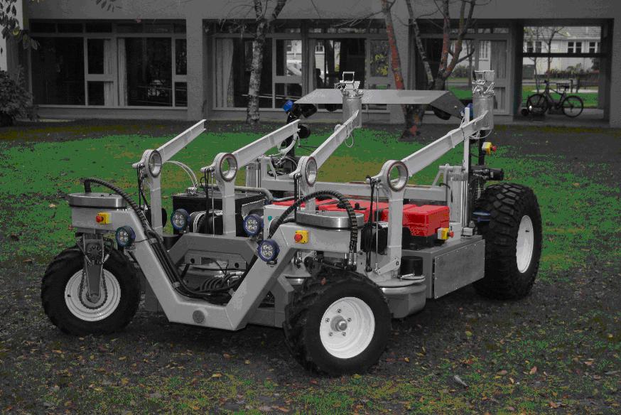
Autonomous Kiwifruit Picker
This is an autonomous 4-wheel drive robotic vehicle which performs the following functions:
• Uses GPS and intelligent vision to navigate kiwifruit orchards; manoeuvring around obstacles such as posts and recognising braces at the end of each row.
• Identifies fruit, discriminating for size and gross defects. Picks the fruit and places it gently into the bin. Checks the fruit level at each point in the bin and adjusts fruit placement to fill the bin evenly.
• Decides when the bin is full, goes to the end of the row and unloads the bin. Searches for and picks up an empty bin with its forks, returns to the last position and resumes picking.
• Operates 24-7, checks for light level and operates floodlights if necessary. Checks for rain or dew and covers the bin with a tarpaulin when this is detected so that picked fruit is protected.
• Goes into secure mode (for example when the fruit is wet), moving the robotic arms to a safe position, switching the unnecessary power systems off, and maintaining power only to the main (monitoring) computer and radio link. Wakes up when appropriate and resumes picking.
• Receives and responds to communications via radio link and uses voice recognition to respond to verbal commands.
• Uses a variety of recovery strategies to deal with faults such as getting stuck, vision becoming obscured, etc.
• Collects data on the fruit yield from a particular orchard.
Future Applications
In existing kiwifruit packhouses, approximately 30% of the fruit is rejected on the basis of size and quality. The fruit growers pay the packhouse a packing fee which is based on the gross tonnage with a fine for rejects. The vision software on the automated picker will be developed to recognise fruit which is undersize, unripe, misshapen or marked. Consequently, more of the fruit going to the packhouse will actually be packed for sale. Pollination is an expensive and difficult operation in kiwifruit orchards and unexplained hive deaths are a considerable worry to orchardists. Consequently, some orchardists apply pollen manually so that they are not reliant on bees. Manual applications do not apply the pollen efficiently. The vision system on the automated kiwifruit robot will be developed to recognise female flowers and apply pollen precisely to the flower in an optimal manner (leaving sufficient room between pollinated flowers for the fruit to develop in an unobstructed way) using a customised pollen delivery system attached to the robot hand. The pruning of kiwifruit vines is another expensive and time-consuming operation for the industry. The autonomous robotic system will be adapted to perform this function. The robotic arms of the system will be adapted to pick other types of fruit such as apples and oranges.
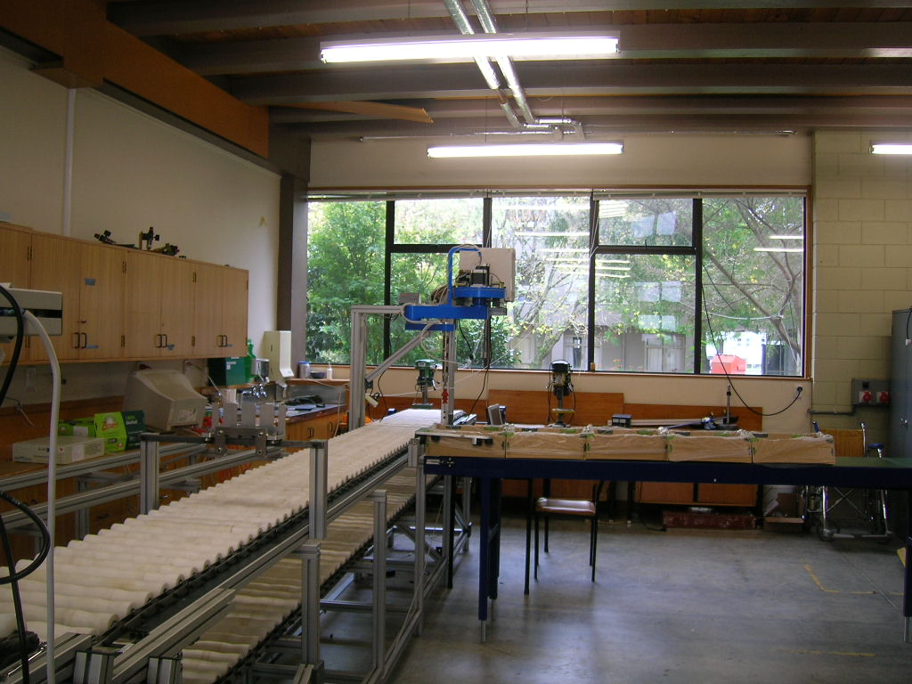
Kiwifruit Packer
This packing line has been built initially with one out of nine robots and one out of four lanes. The completed system (9 robots, 4 lanes), it will pack 250 – 400 trays per hour with only one worker. The fruit goes though the following processes; • Softness measurement to give an equivalent penetromer reading for each fruit.
• Weighing to 0.1g • Visual inspection to grade to Zespri standards including blemishes, shape and colour.
• Soft spot determination. • Labelling – better than 99 out of 100 labels to stick.
• Robotic placement in any of the standard trays, including automatic management of the plix for multilayer trays.
• Automated handling of empty and full trays.
• Overall control of the system using point and click menu’s. The complete system is due to run, doing repack, later this year.
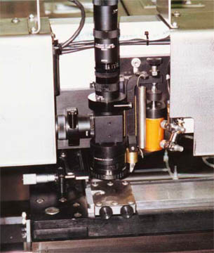
Flat Panel Glass Inspection Systems
This system allowed for extremely rapid inspection of glass panes (100 square centimeters per second) under clean room conditions(class 100). The system, with our proprietary lighting configuration, found defects down to 1 micron in size and classified the type of defect (scratch, chip, bubble etc.). Defect data (type and position) were stored for review by the operator. Review was either performed automatically, in which case the defects were displayed sequentially, or manually, in which case the operator selected the particular defect of interest and a microscopic view of it was displayed. This system was deployed for Corning Glass in Japan.
Glass Compaction Measurement
This system automatically made fine scratches on a sheet of glass held at a reference temperature. Thereafter, the glass passed through some thermal history during the flat panel manufacture process. It was then remeasured and the resultant compaction was reported to an accuracy of a one part in ten million (.03 microns over a typical gauge length of 300 mm). For this application, we developed a 400x microscope with a depth of focus of 4 mm.
Break-edge Machines
These machines automatically ground the sharp edges off Rayban sunglass lenses. We installed 100 of these machines the U.S., Hong Kong, Brazil, Ireland and India.
Graphite Billet Surfacing Machine
This machine used large diamond wheels to grind the surfaces of 1000 lb graphite billets automatically. Automated materials handling was provided. The billets were used for arc furnaces.
Sunglass Lens Inspection System
Bausch and Lomb Rayban sunglass lenses of a particular style (defined by CAD drawing) were accepted and their 3D periphery was measured to a sigma of less than 0.0001 inch. This system used a very high quality CCD lens and 640×480 retina and then compensated mathematically for divergence and fisheye. It provided smoothing to deal with small peripheral chips and, of course operated at sub-pixel accuracies. In fact we were comfortable with edge finding to 0.05 of a pixel. The system was deployed in Hong Kong. (2 Joint Patents with Bausch and Lomb).
Glass Lens Quench System
In order to temper sunglass lenses, they are heated and then air-quenched to provide a skin under compressive stress. All lenses are subjected to having 3/4 inch steel balls dropped on them from a height of 80 inches. Lenses which are imperfectly heated and quenched are likely to shatter, with significant financial consequences. We developed an oven which heated lenses to a very uniform temperature, in continuous pass-through mode. We then developed an air quench system which scoured the boundary layer and provided extremely uniform quenches. We reduced losses by 90% This system was developed for Bausch and Lomb in Rochester, NY.
Apex Blunting Machine
A compact, turbine-driven machine was used to blunt the apex of Rayban sunglass lenses making them less susceptible to chipping. Because of intense space constraints of the station where this operation had to occur, we designed and developed the air turbine and gearing for these units. We built about 100 of them.
Lens Orienting Machine
With sunglass lenses of large base curve, prism is built into the lens to provide a flat optical field. In grinding these lenses, it is necessary to orient them correctly so that the prism works appropriately. We shone a laser though the optical center of the lens and measured its refracted angle as the lens was rotated. This permitted lens orientation and the application of a paint dot.
Development of a Cooling Fluid for Glass grinding
Historically Bausch and Lomb used a glycerine based coolant which was feared to be carcinogenic. We conducted a study of the mechanisms by which diamonds, embedded in a bronze matrix, actually grind the glass and based on this, developed a suitable coolant. The coolant had to be tailored to provide the correct surface lubricity over a reasonable pH range. It also had to inhibit corrosion.
CNC Glass Edging Machine
These machines took glass lens blanks and ground the edge to a desired sunglass lens shape. The edge was bevelled so that the lens could be retained in a grooved eyewire. Edging was held to a circumferential tolerance of 25 microns. An extremely user- friendly software interface allowed unskilled operators quickly to program new lens styles or to load a particular style from the existing library. These machines were deployed in the U.S. and Hong Kong. The project resulted in a patent with Bausch and Lomb.
CNC Eyewire Machine
This machine formed wire frames for sunglass lenses and used visual feedback to control and optimize the shapes of the eyewires. The eyewire around a sunglass lens is a complex three dimensional shape, defined from the shape CAD file and the known base curve of the lens. The wire from which the eyewire is formed has metallurgical properties which vary from roll to roll and from the beginning to the end of a roll. This system used an optical measuring system to assess the length and shape of the eyewire, it then modified the bending metallurgical model to make the final wire conform to specification. It was very important that the wire should not roll as it was bent and a novel bending technique was developed. The machine made an eyewire every two seconds. (2 Joint patents with Bausch and Lomb).
Float Glass Hot Inspection System
This system used sophisticated vision to examine the surface of float glass under extreme temperature conditions (as it came out of the tin bath) and an automated defect marking system to highlight the defective areas. The system distinguished between standard defects such as bubbles, tin, score, stones, etc. it also measured the extent and condition of the knurl using light in the infra red range.
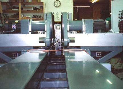
Glass Pane Inspection
This system operated on eight production lines where glass panes were scored and broken. The system measured the edges of the panes and discarded any whose edges or corners had defects larger than a set tolerance. In addition, the system detected markings from the previous process and discarded those panes.
Glass Edge Inspection
When glass is scored and broken, the broken surface of the grass can be examined for indications of improper scoring or breaking. In the development of display panels where ultra clean surfaces are needed, bad breaks lead to vibration and a spray of very fine chips – up to about 100 microns in size. These are electrostatically attracted to the glass and, being pristine, will bond to the glass, making it useless for the laying down of semi-conductors and traces by printing. We developed a system which would optically scan the edge of the glass and determine hackle and chips. We could also measure the depth of the score and provided an RMS measure of smoothness.
Inspection of Ultra Flat discs
Corning Glass developed glass hard-discs (for data storage) which were ultra flat and could therefore potentially store a very high density of data. We developed a system to examine the discs using Nomarsky optics in a microscope and could see sub-micron blemishes. We also developed a grinding technique to bevel the edges of the discs.
Electronic Parts Testers
These units accepted the completed (or board level) controllers for Nissan HVAC automobile systems. The parts were then automatically run through a series of tests which required dials to be set (automatically), buttons to be pushed (automatically) and a range of electrical responses to be measured, including a Nissan proprietary serial coded LAN. In addition visual routines confirmed visual cues supplied by the unit and checked that all icons were unblemished and correctly positioned. All visual routines were written in-house, as primitives in Visual Basic. The units ran 24/7 with an out-of -service tolerance of 2 hours.
Inspection of Nissan instrument panels for automobiles
These instrument clusters contained speedometers, odometers, gauges and warning icons. We provided two robots which moved the cameras to learned locations and performed functions which included the following; icon checking (on/off) and quality and the determination of needle angle to within 15 minutes of arc. The application also required fairly subtle tests for acceptable color ratios. The robots were 2-axis Humbl’s which we built.
Parts management for the testing of Flasher units for GM
This application used one of our robots to move parts through a test sequence, stamp them appropriately or discard them.
Parts feeders for a manufacturer of plugs
The parts were bowl fed and then visually checked for any malformation. They were then fed into a jig for insertion.
Materials handling for a manufacturer of routed doors
This system managed a set of five CNC routers, with their nesting software. Boards ranging in size from 8×4 feet to 10×5 feet by 3/4 thick were picked up from any of 5 dedicated stacks. They were then transported to the appropriate router and placed correctly on the vacuum table. At the end of the asynchronous routing process, the residue was picked up. By communication with the control software, the robotic system knew where the good parts were in the frame and what was scrap. It operated appropriate suction cups so that the scrap could be dropped and the good pieces bar coded and passed to the output conveyor. The robot envelope was 120 feet long by 20 feet wide.
Board packing
Tongue and groove hardwood boards of random length up to seven feet and random orientation were received on a conveyor travelling at 100 fpm. Two widths of board were present and the boards were randomly distributed over a 48 inch wide conveyor. Some of the boards were inverted, signalling that they shouldn’t be packed. Some of the boards were rotated so that they had to be re-rotated by about 180 degrees before packing. The boards were to be packed with tongues and grooves appropriately nested and such that each box had the desired total board length to +/- 2.5%. Further, the top layer of boards had to be inverted. At any robot cycle the best strategy had to be followed because the cycle could not be empty and the best pick had to be made from those planks within the robot’s reach. Further, the assembly of the wood in the box was something in the nature of a 3D puzzle. This task was accomplished by using sets of two interacting cartesian robots under a Master Control which was capable of handling and queuing 16 sets of two robots. Of course, by the time a specific board travelled 150 feet to the last robots, about 90 seconds had elapsed. Further, the system fed and removed the corrugated boxes automatically and scheduled the time for such transfer, without letting robots stand idle unnecessarily. Provision also had to be made for accidents so that the system was self policing and could recover. This project took a year.
Optimizing the ripping of oak boards
Oak boards up to 16 feet long and up to 22 inches wide were fed transversely on a chain conveyor to an inspection station. The boards were examined by 4 colour cameras which determined the curvature of the board and its dimensions and gross blemishes. The boards moved on oblique rollers to hold them against a fence. The control system could set the position of this fence. From a position against this fence, the boards were then fed longitudinally into a gang rip saw. The settings of the spaces between the blades were varied and represented acceptable widths of the rips. The control system set the fence so that the optimum yield was obtained from each board. This was a hostile environment, with temperatures from 0F to 100F, lumberjacks and a lot of dust.
Examining rough rips for defects in order to cut out Knots and Blemishes
After boards are ripped, the next stage was to cut them into acceptable lengths. There are standard lengths but they must be clear of knots, shake, wane, split and bark. We developed a system which performed acceptably on visual data alone. This competed successfully against a system which used XRays and multi-spectral visual analysis.
Respirometer
We developed a system to provide simulated breaths and coughs for the National Institute Occupation Safety and Health. It featured a large piston with programmable motion, with discharge through a venturi so that instantaneous velocity could be measured and integrated.
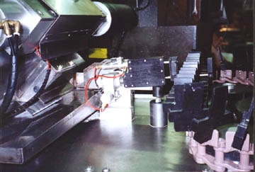
Spinning of Gas bottles
Steel gas bottles weighing up to 80 pounds were presented to our system as open ended steel tubes. A cartesian robot placed cylinders sequentially into one of three gas furnaces running at 2400F. It then selected the one with the longest residence time and placed it in the collet of a large lathe. Spinning blocks were manipulated under hydraulic control to form a hemisphere on the end of the tube. The completed part, with the end still yellow hot, was then removed by a second robot and slid over the stud of a bottoming press to form the dunt. The unit was then removed and discarded on a conveyor to cool. One robot had to work continuously in front of the blast furnace which required extreme measures to protect it.
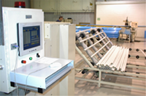
Plastic Tube Cutting and Drilling
Plastic tubes of several cross sections and diameters from 3/4 to 3 inches and length up to 20 feet were placed in a large hopper. The hopper had a feed system which fed one tube at a time to a conveyor which then fed into the machining unit. This cut tubes to a programmed length and drilled holes at programmed positions.